Engine-off operation
The inverter carries eligible loads while battery energy remains above the selected reserve. Fans and thermal-management loads still consume energy.
 MODULAR INFRASTRUCTURE / HYBRID POWER
A mobile generator-and-battery concept for field operations, temporary site power and a future external-power version of DryForce.
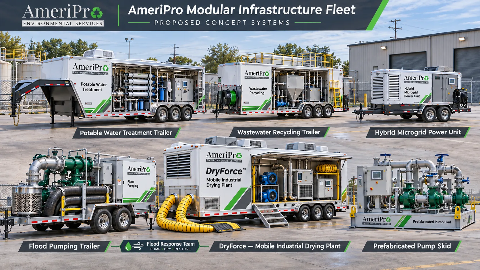
The baseline uses an interlocked source selector and dedicated generator-fed battery charger. Generator and inverter outputs are not assumed to operate in parallel.
The inverter carries eligible loads while battery energy remains above the selected reserve. Fans and thermal-management loads still consume energy.
The generator carries site load and a controlled charger. Charging backs off as load rises, subject to selected equipment limits.
Peak shaving, grid interaction and seamless transfers require a different validated controls / protection design. No summed output rating is claimed here.
The current DryForce study allocates 19.7 kW of connected real power. Its voltage, phase, starting demand and protective interfaces are unresolved. The preset below is an energy-planning case, not a compatibility approval.
An external-power DryForce variant would retain its equipment protections and replace or omit its onboard generation only after coordinated design. Do not subtract its generator weight or cost from the existing design until that variant is defined. The diesel-driven MFP-500 does not become an electrically driven pump by connecting this trailer.
Compare battery energy and steady-state recharge. Results exclude transfer time, warmup, transient starting, aging and fuel consumption. All presets are illustrative.
DC energy window = nominal kWh × (upper SOC − reserve SOC) / 100. Usable AC energy = DC window × discharge efficiency. Average demand = site average + auxiliaries. Engine-off hours = usable AC energy / average demand.
Charger AC input = minimum(charger input limit, maximum(0, generator kW × dispatch fraction − average demand)). Recharge hours = DC window / (charger AC input × charge efficiency). Long-run generator-on equivalent = 24 × recharge hours / (recharge hours + engine-off hours). This is a repeated-cycle equivalent, not the actual first calendar day's engine runtime.
The model checks peak running real power plus auxiliaries against both sources independently. It does not model peak duration, charger transients, kVA, voltage dip, power factor, phase imbalance, motor starting or battery discharge C-rate. No fuel savings, fuel runtime or uninterrupted transfer capability is predicted.
22 ft nominal equipment body × 8 ft 6 in external width. Proposed packaging only; overall road length and axle / hitch arrangement remain open.
Initial loaded mass allocation: 9,200 lb against an 11,000 lb design ceiling, leaving 1,800 lb unallocated reserve. That fits a 9,990 lb GVWR with 790 lb to spare, keeping it non-CDL like the MWTP-50C; plating at the 11,000 lb ceiling would require Class A CDL drivers behind a typical 1-ton pickup.
Equipment tags, mass budget, electrical boundaries, control modes and validation gates.
Read design notes →$174,000 base allowance + 20% contingency = $208,800 illustrative concept budget. No vendor quotes.
Read BOM & exclusions →Develop an external-power DryForce option and validate its voltage, starting and protection requirements.
Review DryForce load study →Background: Atlas Copco hybrid energy-storage overview and Caterpillar generator-sizing guidance. These support general design principles, not the AmeriPro equipment targets or budget.